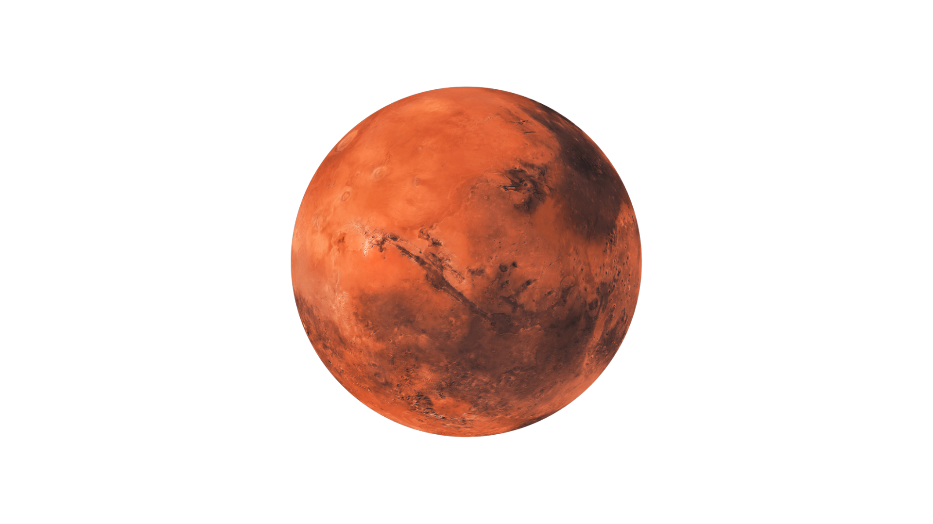
Mission Corridor: Earth to Mars
Earth-Mars Reference Distance225,000,000 km
Simulated Distance Covered0 km
Mission Progress0.00%
Current Mission PhaseStandby
Live Clock Synchronization
UTC--
Earth Atomic Time Proxy--
CST Mission Time00:00:00
Interstellar Clock--
Voyager 1 Reference--
Voyager 2 Reference--
Earth Rotation Clock--
Mars Sol Clock--
Voyager 1 and Voyager 2 are used as deep-space timing reference proxies. They do not physically steer the craft; they represent multi-clock synchronization.
Speed and Target Readings
Current Speed0 mph
Speed as % of Light0.000%
Parker Solar Probe Benchmark430,000 mph
Stage 1 Target0.080% c ≈ 536,000 mph
Stage 2 Target0.100% c ≈ 670,600 mph
Long Goal1.000% c ≈ 6,706,000 mph
Navigation and Motion Inputs
Earth Rotation Speed Proxy1,670 km/h
Mars Rotation Speed Proxy
Earth-Mars GeometryMedium
Heading Error0.00°
Trajectory Correction PulseStandby
Estimated Cruise Time at Current Speed--
Stage 1: Fission Base Power
E = mc² | P = dE/dt
Steady energy tank for clocks, ionization, magnets, cooling, and pulse recharge.
Elements and Materials
UFuel
ThFuel
ZrClad
BAbsorb
HfControl
WShield
Power Output0 MW
Core Temperature0 K
Shield Load0%
Stage 2: Fusion Augmentation
Pf = n²<σv>Ef
Advanced boost layer. In this simulation it acts as future assist, not required for first 0.080% c test.
Elements and Materials
DFuel
TFuel
LiBlanket
BeNeutron
WWall
SiCCeramic
Fusion Assist0%
Neutron Shield Stress0%
Thermal MarginStable
Stage 3: Ionization and Plasma
iℏ∂ψ/∂t = Ĥψ | ωp = √(ne²/ε₀me)
Neutral propellant becomes charged plasma working mass.
Elements and Materials
XeProp
ArProp
KrProp
LiMPD
WElec
Al₂O₃Insul
Ionization Level0%
Plasma Density0
Propellant Flow0 g/s
Stage 4: Particle Separation / Siphon Entry
F = q(E + v × B) | ωc = qB/m
Charged particles are separated from neutrals. This is the entrance of the magnetic siphon path.
Elements and Materials
CuCond
CGraph
YYBCO
BaYBCO
OYBCO
REREBCO
Separation Efficiency0%
Neutral Rejection0%
Siphon Entry Pressure0
Stage 5: Magnetic Siphon Vortex
∇·E = ρ/ε₀ | ∇·B = 0 | ∇×B = μ₀J + μ₀ε₀∂E/∂t
Plasma is compressed, organized, rotated, and prepared for rear exhaust.
Elements and Materials
REREBCO
YYBCO
BaYBCO
CuCoil
NbSupport
TiSupport
CHousing
Magnetic Field0 T
Compression Ratio0.00
Vortex Stability0%
Stage 6: Pulse Energy Gate
E = hf | P = Epulse / Δt
Creates short impulse events. Antimatter is treated as theoretical only.
Elements and Materials
BShield
CDLC
WShield
AuRad
SiChip
AlCase
Pulse ModeStandby
Pulse Energy Proxy0 GJ
Timing LockWaiting
Stage 7: Magnetic Nozzle
F = ṁve + (Pe − Pa)Ae | vA = B/√(μ₀ρ)
Final plasma compression and direction. Heat and plasma are released rearward.
Elements and Materials
WNozzle
ReAlloy
HfHfC
ZrZrC
TaTaC
SiSiC
CGraph
Nozzle Temperature0 K
Exhaust Velocity Proxy0 km/s
Thrust Vector Error0.00°
Stage 8: Plasma Exhaust / Heat Rejection
F = ṁve | q = εσA(T⁴ − Tspace⁴)
Rear exhaust removes heat and produces thrust. Exhaust color becomes live diagnostic feedback.
Elements and Materials
LiPlasma
XePlasma
ArPlasma
CC-C
SiCCeram
BShield
WSink
Exhaust Color StateDark / Standby
Heat Rejected Rearward0%
Radiation Rear Bias0%
Material Protection by Region
Front ShieldC-C + carbon foam + Al₂O₃ / SiC coating
Reactor ShieldW + B₄C + LiH + Hf control
Ionization ChamberW electrodes + Al₂O₃ insulators
Siphon VortexREBCO/YBCO + Cu + NbTi + C housing
Nozzle ThroatW-Re + HfC + ZrC + TaC + SiC
Rear Heat ZoneC-C + graphite + DLC + SiC + W sink
Compression / Heat / Cold Conversion
Ionization Heating0%
Magnetic Compression0%
Nozzle Thermal Load0%
Cryogenic Magnet Demand0%
Rear Heat Escape0%
Cold conversion means cryogenic support for superconducting magnetic stages. Heat must still be rejected rearward or radiated away.
Exhaust Diagnostic Color System
Blue / WhiteIdeal high-energy plasma
Orange / RedToo much heat retained
Purple FlickerMagnetic instability
Dim BlueWeak ionization
Erratic MulticolorTiming mismatch
Current DiagnosticStandby